Efficient compression for event-based data
Datasets grow larger in size
As neuromorphic algorithms tackle more complex tasks that are linked to bigger datasets, and event cameras mature to have higher spatial resolution, it is worth looking at how to encode that data efficiently when storing it on disk. To give you an example, Prophesee’s latest automotive object detection dataset is some 3.5 TB in size for under 40h of recordings with a single camera.
Event cameras record with fine-grained temporal resolution
In contrast to conventional cameras, event cameras output changes in illumination, which is already a form of compression. But the output data rate is still a lot higher cameras because of the microsecond temporal resolution that event cameras are able to record with. When streaming data, we get millions of tuples of microsecond timestamps, x/y coordinates and polarity indicators per second that look nothing like a frame but are a list of events:
#  time, x, y, polarity
[(18661,  762, 147, 1)
 (18669, 1161,  72, 1)
 (18679, 1073,  23, 0)
 (18688,  799, 304, 0)
 (18694,  234, 275, 1)]
File size vs reading speed trade-off
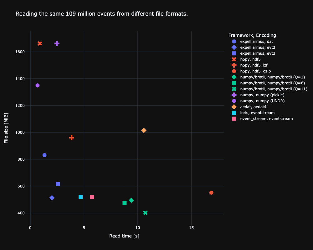
So how can we store such data efficiently? A straightforward idea is to resort to formats such as hdf5 and numpy and store the arrays of events directly. But without exploiting any structure in the recorded data, those uncompressed formats end up having the largest file footprint. For our example automotive dataset, this would result in some 7-8 TB of data, which is undesirable. Event camera manufacturers have come up with ways to encode event streams more efficiently. Not only are we concerned about the size of event files on disk, but we also want to be able to read them back to memory as fast as possible! In the following figure we plot the results of our benchmark of different file type encodings and software frameworks that can decode files.

Ideally, we want to be close to the origin where we read fast and compression is high. The file size depends on the encoding, whereas the reading speed depends on the particular implementation/framework of how files are read. In terms of file size, we can see that numpy doesn’t use any compression whatsoever, resulting in some 1.7GB file for our sample recording. Prophesee’s EVT3 and the generic lossless brotli formats achieve the best compression. In terms of reading speed, numpy is the fastest as it doesn’t deal with any compression on disk. Unzipping the compressed events from disk on the other hand using h5py is by far the slowest. Using Expelliarmus and the EVT2 file format, we get very close to numpy reading speeds while at the same time only using a fourth of the disk space.
Details on Prophesee data formats
Prophesee is one of the major event cameras vendor. Their cameras use three main encoding algorithms for their data: DAT, EVT2 and EVT3. By encoding algorithm it is identified the process by which an event sensed by the camera, consisting in a tuple (timestamp, x_address, y_address, polarity), is encoded to a binary data format.
DAT

The DAT format encodes an event to a 64 bits word. However, when reading the events from the binary file in chunks of 64 bits on a Little Endian (LE) machine, the image above does not correspond to reality. The following representation, instead, results to be correct:
    4 bits     14 bits     14 bits           32 bits
  ---------------------------------------------------------
 | Polarity | Y address | X address |       Timestamp      |
  ---------------------------------------------------------
Each DAT recording can store an event stream lasting at most 1 hour and 12 minutes, since the timestamp maximum value is 4294967295 μs (unsigned 32 bits maximum value).
The C++ code to decode a DAT event is the following:
/** Function that decodes a DAT event to a (ts, x, y, p) tuple.
 *
 *  @param[in]  buff    64 bits buffer read from the DAT file.
 *  @param[out] ts      64 bits timestamp.
 *  @param[out] x       16 bits x address.
 *  @param[out] y       16 bits y address.
 *  @param[out] p       8 bit polarity.
 *
 *  @return     isEvent True when an event has been decoded.
 */
void decode_event(
    const uint64_t buff,
    int64_t& ts,
    int16_t& x,
    int16_t& y,
    uint8_t& p
    ) {
    const uint64_t mask_32b = 0xFFFFFFFF;
    const uint32_t mask_14b = 0x3FFF;

    const uint32_t upper_32b = (buff >> 32); // Upper 32 bits.
    const uint32_t lower_32b = (buff & mask_32b); // Lower 32 bits.

    ts = lower_32b; // Timestamp.
    x = upper & mask_14b; // X address.
    y = (upper >> 14) & mask_14b; // Y address
    p = upper >> 28; // Polarity.

    return true;
}
One can notice that the events are not compressed but simply encoded to a compact binary format.
EVT2
Here things get interesting. For EVT2, each event is encoded to a 32 bits word; in particular, two kinds of events are used: CD_OFF and CD_ON, respectively associated with negative and positive polarity events.
A CD event is structured in the following way:
          4 bits          6 bits      11 bits     11 bits
  ---------------------------------------------------------
 | Event type (on/off) | Timestamp | X address | Y address |
  ---------------------------------------------------------
- the first 4 bits are the event type. One might see this as the value of the polarity bit.
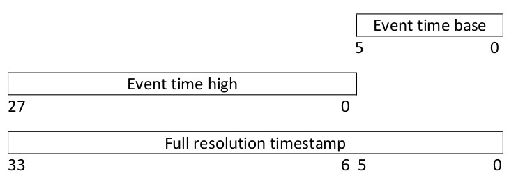
- then, 6 bits are dedicated to the timestamp. However, the full resolution time stamp is given by this merged with the upper 28 bits passed in another event, called
TIME HIGH, as it is shown in the following:

Hence, the lower 6 bits are passed during a CD_* event, while the upper 28 bits are passed during a TIME HIGH event, which is structured in the following way:
       4 bits                    28 bits
  --------------------------------------------------------
 | Time high code |             Timestamp                 |
  --------------------------------------------------------
Since the lower 6 bits change more frequently than the upper ones, many events can be encoded in CD_* ones before sending out a new TIME_HIGH reference.
Probably the reader would like to see some code, and here it comes:
/** Function that decodes an EVT2 event to a (ts, x, y, p) tuple.
 *
 *  @param[in]   buff    32 bits buffer read from the DAT file.
 *  @param[out]  ts      64 bits timestamp.
 *  @param[out]  x       16 bits x address.
 *  @param[out]  y       16 bits y address.
 *  @param[out]  p       8 bit polarity.
 *
 *  @return      isEvent True when an event has been decoded.
 */
bool decode_event(
    const uint32_t buff,
    int64_t& ts,
    int16_t& x,
    int16_t& y,
    uint8_t& p
    ) {
    const uint32_t mask_28b = 0xFFFFFFF;
    const uint32_t mask_11b = 0x7FF;
    const uint32_t mask_6b = 0x3F;

    static uint64_t tsHigh = 0; // Static so that ts_high value is
                                // remembered the next time the
                                // function is called.
    bool isEvent = false;

    uint8_t evt_type = buff >> 28;

    switch (evt_type) {
        case 0x0: // CD_OFF
        case 0x1: // CD_ON
            ts = (tsHigh << 6) | ((buff >> 22) & mask_6b);
            x = (buff >> 11) & mask_11b;
            y = buff & mask_11b;
            p = evt_type;
            isEvent = true;
            break;

        case 0x8: // TIME_HIGH
            tsHigh = buff & mask_28b;
    }

    return isEvent;
}
The version that actually works is available here.
EVT3
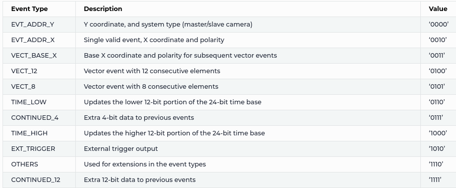
With EVT3, data compression is higher: events are encoded to 16 bits words but there ate many more event types, as it is shown in the following table, taken from Prophesee documentation.

The logic behind EVT3 is the following: a new event is registered when the x address changes. From this principle, one has to register a camera event when one of the following three events appear in the stream:
EVT_ADDR_X: single event with thexcoordinate encoded to it, together with polarity. The timestamp andyaddress have been passed in previous events. This event is structured as follows:
       4 bits         1 bit             11 bits
  --------------------------------------------------------
 | EVT_ADDR_X code | Polarity |        X address          |
  --------------------------------------------------------
VECTOR_12: 12 events vectorized in a single data buffer. In particular, starting from a basexaddress, denoted withbaseXin the code, all the events in this buffer are placed in the next 12 horizontal pixels (i.e. withyfixed andxvarying) starting frombaseX:
        4 bits         1 bit             11 bits
  --------------------------------------------------------
 | VECT_BASE_X code | Polarity |      Base X address      |
  --------------------------------------------------------
The mask vector is encoded in the following way:
       4 bits                     12 bits
  --------------------------------------------------------
 | VECTOR_12 code |            Validity mask              |
  --------------------------------------------------------
Not all the events in the vector are valid: only the ones to which a bit equal to 1 in the validity mask depicted above is associated! For this reason, a validity mask made up of 12 bits is provided: if we consider the mask a vector of 12 integers of value either 0 or 1, the pseudo-code to interpret it is the following:
for (int i=0; i<12; i++) {
    if (mask[i] == 1) {
        isEvent = true;
        xAddr = baseX + i;
    } else {
        isEvent = false;
    }
}
An example of vectorized event is the following:
   4 bits                   12 bits
  --------------------------------------------------------
 | VECTOR | 1 | 0 | 1 | 0 | 0 | 1 | 0 | 0 | 0 | 0 | 0 | 1 |
  --------------------------------------------------------
This leads to the following events being encoded to output (keep in mind that we are reading starting from the LSB, i.e. from the right side of the mask):
              Event associated to mask bit #0
  --------------------------------------------------------
 | Timestamp |   baseX + 0   |  y address  |   polarity   |
  --------------------------------------------------------

              Event associated to mask bit #6
  --------------------------------------------------------
 | Timestamp |   baseX + 6   |  y address  |   polarity   |
  --------------------------------------------------------

              Event associated to mask bit #9
  --------------------------------------------------------
 | Timestamp |   baseX + 9   |  y address  |   polarity   |
  --------------------------------------------------------

              Event associated to mask bit #11
  --------------------------------------------------------
 | Timestamp |   baseX + 11  |  y address  |   polarity   |
  --------------------------------------------------------
Since we are dealing with a 12 bit buffer, the pseudo-code is actually the following:
for (int i=0; i<12; i++) {
    if (mask & 1) { // Reading the LSB.
        isEvent = true;
        xAddr = baseX + i;
    } else {
        isEvent = false;
    }
    mask = mask >> 1; // Moving on to the next bit.
}
VECTOR_8: same asVECTOR_12but with 8 events encoded in the vector.
What about timestamps? Well, now the timestamp is encoded to a 24 bits data buffer, separated in two events: TIME_LOW for the lower 12 bits, TIME_HIGH for the upper 12 bits. Each of these events is encoded as follows:
         4 bits                     12 bits
  --------------------------------------------------------
 | TIME HIGH/LOW code |            Timestamp              |
  --------------------------------------------------------
Hence, we need to glue together these values to get the full timestamp, as it is shown in the following picture taken from Prophesee documentation.

The full C++ code to handle EVT3 events is shown in the following.
/** Function that decodes an EVT3 event to a (ts, x, y, p) tuple.
 *
 *  @param[in]   buff    16 bits buffer read from the DAT file.
 *  @param[out]  ts      12 entries array of 64 bits timestamps.
 *  @param[out]  x       12 entries array of 16 bits x addresses.
 *  @param[out]  y       12 entries array of 16 bits y addresses.
 *  @param[out]  p       12 entries array of 8 bit polarities.
 *
 *  @return      isEvent True when an event has been decoded.
 */
bool decode_event(
    const uint16_t buff,
    int64_t ts[12],
    int16_t x[12],
    int16_t y[12],
    uint8_t p[12]
    ) {
    const uint16_t mask_12b = 0xFFF;
    const uint16_t mask_11b = 0x7FF;

    static uint64_t tsHigh, tsLow = 0;
    static int16_t baseX = 0; // Base x address for vectorized events.
    static int16_t baseY = 0; // To remember the y value across events.
    static int8_t baseP = 0; // To remember the p value across events.

    int16_t numVectEvts = 0;

    bool isEvent = false;

    /** Resetting the polarity array. Our policy is that polarity can be
     *  either 0 or 1; by setting the elemnts in the polarity vector to
     *  a number larger than 1, we tell the user that those are non valid
     *  events.
     */
    int16_t i=0;
    for (i=0; i<12; i++)
        p[i] = 99;

    uint8_t evt_type = buff >> 12;

    switch (evt_type) {
        case 0x0: // EVT_ADDR_Y.
            baseY = buff & mask_11b;
            break;

        case 0x2: // EVT_ADDR_X.
            ts[0] = (tsHigh << 12) | tsLow;
            x[0] = buff & mask_11b;
            y[0] = baseY;
            p[0] = (buff >> 11) & 1;
            isEvent = true;
            break;

        case 0x3: // EVT_BASE_X.
            baseX = buff & mask_11b;
            baseP = (buff >> 11) & 1;
            break;

        case 0x4: // VECT_12.
            numVectEvts = 12;
        case 0x5: // VECT_8;
            if (numVectEvts != 12)
                numVectEvts =  8;
            int16_t mask = buff & mask_12b;
            for (i=0; i<numVectEvts; i++) {
                if (mask & 1){
                    ts[i] = (tsHigh << 6) | tsLow;
                    x[i] = baseX + i;
                    y[i] = baseY;
                    p[i] = baseP;
                    isEvent = true;
                }
                mask = mask >> 1;
            }
            break;

        case 0x6: // TIME_LOW.
            tsLow = buff & mask_12b;
            break;

        case 0x8: // TIME_HIGH.
            tsHigh = buff & mask_12b;
    }

    return isEvent;
}
This code is just for demonstration purposes, it won’t actually work, since we need to take care of other things such as timestamp overflows. A working version of this code is provided here.
Capable frameworks
The authors of this post have released Expelliarmus as a lightweight, well-tested, pip-installable framework that can read and write different formats easily. If you’re working with DAT, EVT2 or EVT3 formats, why not give it a try?
Summary
When training spiking neural networks on event-based data, we want to be able to feed new data to the network as fast as possible. But given the high data rate of an event camera, the amount of data quickly becomes an issue itself, especially for more complex tasks. So we want to choose a good trade-off between a dataset size that’s manageable and reading speed. We hope that this article will help future groups that record large-scale datasets to pick a good encoding format.
Authors
- Gregor Lenz is a research engineer at SynSense, where he works on machine learning pipelines that can train and deploy robust models on neuromorphic hardware. He hold a PhD in neuromorphic engineering from Sorbonne University in Paris, France.
- Fabrizio Ottati is a Ph.D. student in the HLS Laboratory of the Department of Electronics and Communications, Politecnico di Torino. His main interests are event-based cameras, digital hardware design and neuromorphic computing. He is one of the maintainers of two open source projects in the field of neuromorphic computing, Tonic and Expelliarmus, and one of the founders of Open Neuromorphic.
- Alexandre Marcireau.
Comments
The aedat4 file contains IMU events as well as change detection events, which increases the file size artificially in contrast to the other benchmarked formats.